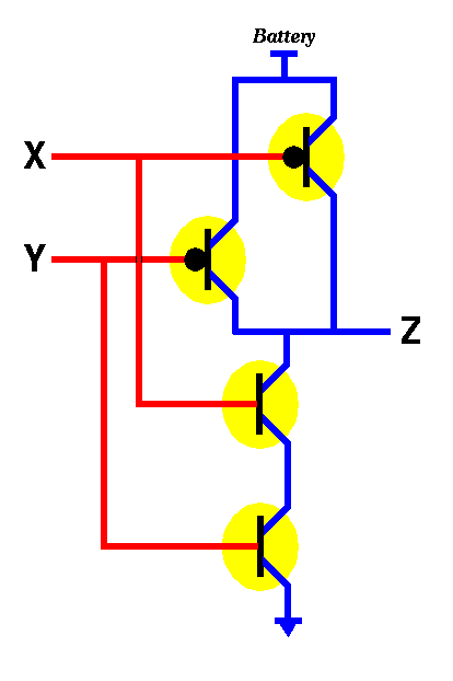


Thus, this MOSFET version of the RTL inverter also has the same issue. Current through the resistor (and the equivalent resistance of the MOSFET) means power dissipation, and this is constant. Even after the node falls to 0V, there is still a connection between Vcc and GND through the resistor R and MOSFET. In this case, the output voltage will fall to 0V (given the capacitance C was previously charged due to a previous "1" output state). This means that the NMOSFET is "on" and current is flowing through it. If the desired output at Vout is a logic "0", it can be assumed that the input "Vin" is high at a logic "1". Given the circuit, the same logic applies. Simulate this circuit – Schematic created using CircuitLab Another difference is that there is a capacitance at the output node to GND in this schematic, but that does not affect the answering of the question. As shown below, the resistor-transistor logic (RTL) inverter has a very similar topology, except for the absence of a resistor on the base (gate in this case, as it is an n-channel MOSFET). Allow me to expand upon this with the MOSFET equivalent. As others have stated, the first topology consumes constant power when the output of the inverter is low (logic "0"). Similarly it will have a much lower impedance output when in the low state than when in the high state.ĬMOS does come at the price of needing two different types of transistor, that does complicate the fabrication process but it's a small price to pay for the advantages mentioned above. A device that relies on a pull-up resistor (or weak transistor) will have a fast fall time, but a much slower rise time. Thirdly because CMOS actively drives the output in both directions, the performance is closer to symmetrical. Secondly CMOS has the huge advantage of very low power consumption when not switching, because the gate of a CMOS transistor is essentially a capacitor and passes no DC current and only one of the transistors is switched on at a time so there is no significant DC current by that path either. In the days when pull-ups were used in IC design they were frequently done with weak transistors instead of resistors. Firstly, it's counter-intuitive to someone used to designing with discrete components, but in IC design transistors are cheap and everything else is expensive. So now we have a (very) simplified expression for OUT1: Input0 != Input1.(Input1 != 0) is equivalent to simply Input1 Now we know that A != 0 is equivalent to A.Here (Operation != Operation) is the constant "0".Input0 != Input1 != (Operation != Operation).Input0 != Operation != Input1 != Operation.(A != B) != (C != D) we can drop parentheses, rearrange in any order, etc.(Input0!=Operation) != (Input1!=Operation).so it should be clear the order of inputs (which pairs get XOR'd first) just doesn't matter.the output is "0" if the number of "1" inputs is even.the output is "1" if the number of "1" inputs is odd,.Again, draw a truthtable if you need clarity.I'll also introduce the 3-variable equivalence: Here, we'll exploit the fact that A&1 is equivalent to simply A (draw the truth table for each if you can be bothered). So now we've reduced OUT0 to a single gate (an XNOR being "=").1!= (Input0!=Operation) is equivalent to.Out0: 1!= (Input0!=Operation) (parentheses added for clarity) Now we can really get going with your expressions: So it should be clear that A != A is equivalent to the constant "0", and also A = A is equivalent to the constant "1". So here it's clear that for the expression (A != 1) we can simply substitute !A. In this case we just select the relevant rows only from the truth table, e.g. Now either of A, B can be constants (fixed 1 or 0) rather than variable inputs. The following are all equivalent expressions (all have an identical truth table) further reductions left as exercise for the readerīoolean expressions have a large number of substitutions which you can swap in, some may be more transistor-efficient.įor XOR ("!="), the truth table is as follows: A Out1 can be simplified to Input0 != Input1 (i.e.Out0 can be simplified to Input0 = Operation (i.e.


 0 kommentar(er)
